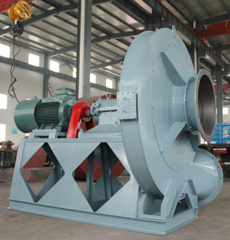
Introduction to a method for manufacturing an exhaust gas treatment fan
Release time:
2021-09-04
Currently, exhaust gas treatment typically uses specialized fans. Existing exhaust treatment fans, after long-term filtration, tend to accumulate a large amount of impurities, leading to fan blockage, which reduces the effectiveness of exhaust treatment and shortens the lifespan of the specialized fans. Additionally, as a complete unit, the fans are not easy to disassemble and are difficult to take apart.
Exhaust gas refers to the toxic and harmful gases emitted by humans during production and daily life, especially from chemical plants, steel mills, pharmaceutical factories, coking plants, and oil refineries. Exhaust gas has a strong odor, severely pollutes the environment, and affects human health. It contains various pollutants with very complex physicochemical properties and varying degrees of toxicity. The exhaust gas emitted from fuel combustion contains sulfur dioxide, nitrogen oxides, hydrocarbons, etc. Due to the different raw materials and processes used in industrial production, various harmful gases and solid waste are emitted, including heavy metals, salts, and radioactive substances. Currently, exhaust gas treatment typically uses specialized fans.Exhaust gas treatment fanAfter long-term filtration treatment, a large amount of impurities can easily accumulate, leading to fan blockage, thereby reducing the effectiveness of exhaust gas treatment and shortening the lifespan of the specialized fan. Additionally, as a whole device, the fan is inconvenient to disassemble and difficult to take apart.

To address this, technicians have provided a solution.Exhaust gas treatment fanTo achieve the above objectives, the exhaust gas treatment fan adopts the following technical scheme: an exhaust gas treatment fan includes a first fixed plate, with a second fixed plate fixedly connected to the upper left and upper right of the first fixed plate. The upper ends of the two second fixed plates are fixedly connected to the fan. A retractable storage device is located at the upper left of the first fixed plate, which passes through the lower part of the fan's outer surface and extends into the fan. A filter screen is fixedly connected to the middle of the fan's inner cavity, an air intake pipe is fixedly connected to the upper left side of the fan's outer surface, an air outlet is located at the right end of the fan, a rotating device is located at the left end of the fan, and a first through groove is located at the upper right side of the fan's outer surface. The first retractable rod is movably connected to the output end of the first retractable power machine, and a storage box is fixedly set at the upper end of the first retractable power machine. The first retractable power machine is fixedly connected to the upper left end of the first fixed plate, connecting the retractable storage device with the first fixed plate. The rotating device includes a motor, with the output end of the motor fixedly connected to the first rotating rod. The fan is fixedly installed on the right side of the outer surface of the first rotating rod, and the motor is fixedly connected to the middle of the left end of the fan, connecting the rotating device and the fan together. A U-shaped frame is fixedly installed at the lower end of the first connecting plate, and the lower part of the inner cavity of the U-shaped frame is movably connected to the stirring cylinder through a rotating shaft. The upper part of the left end of the first connecting plate is movably connected to the second retractable power machine through a rotating shaft, and the left end of the second retractable rod is movably connected to the second retractable power machine. The first retractable power machine is electrically connected to the first retractable rod, and the second retractable power machine is electrically connected to the second retractable rod. The swinging and beating device is located on the right side of the filter screen.
Compared with the prior art, the aboveExhaust gas treatment fanhas the following beneficial effects: 1. The second retractable power machine of the exhaust gas treatment fan drives the second retractable rod to extend, thereby moving the stirring cylinder to the left to contact the surface of the filter screen; when the second retractable rod retracts, it drives the stirring cylinder back to the initial position; when the stirring cylinder is in a left-right swinging state, it can repeatedly beat the surface of the filter screen, causing impurities on the filter screen to fall into the storage box for collection, preventing the mesh holes of the filter screen from clogging and improving the filtering effect of the filter screen. 2. The exhaust gas treatment fan shortens the first retractable rod by driving it with the first retractable power machine, allowing the storage box to be separated from the fan when moving down, facilitating the cleaning of impurities in the storage box without the need to disassemble the fan, providing convenience for users and improving the practicality of the fan.
Related News


