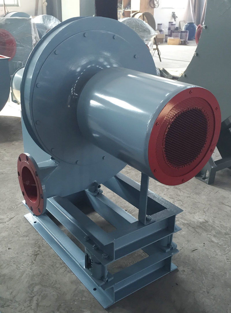
What is the structure of the axial flow fan's adjustment?
Release time:
2022-01-19
The adjustment axial flow fan of the induced draft fan generally consists of an air intake, housing, rotor, expander, coupling and protective frame, adjustment device and actuator, hydraulic and lubrication oil supply device and measuring instrument, fan outlet expansion joint, inlet matching flange, and outlet matching flange. As shown in Figure 32, it is the structure of a blade-adjustable axial flow induced draft fan.
How is the structure of the induced draft fan's adjustable axial flow?Induced draft fanWhat is the structure like?
The adjustable axial flow guide fan of the induced draft fan generally consists of an air inlet, casing, rotor, expander, coupling and protective frame, adjustment device and actuator, hydraulic and lubrication oil supply device and measuring instrument, fan outlet expansion joint, inlet matching flange, and outlet matching flange. As shown in Figure 32, this is the structure of a blade-adjustable axial induced draft fan.

What is the form of the collector (inlet) of the induced draft fan?
There are five types of collectors: cylindrical, conical, combined, streamlined, and scaled body, among which the streamlined type is the most widely used currently. It is important to ensure the proper function of the oil flow device to ensure that the airflow is evenly introduced, filling the inlet part of the impeller, resulting in minimal resistance loss at the inlet.
Induced draft fanWhat is the working principle of the adjustable axial flow fan?
The working principle of the axial fan is based on wing theory. Wing theory states that the shape of the cross-section of an aircraft wing (which is triangular) causes the air flowing over the top surface of the wing to move faster than the air flowing beneath it. As a result, the air pressure on the upper surface of the wing is lower than that on the lower surface. This pressure difference generates lift for the aircraft. The different curvatures above and below create different air pressures, resulting in upward movement. The working principle is as follows:
The gas enters the impeller at an angle of attack (for example, the angle between the wing chord and the average relative velocity of the airflow), generating lift at the back of the wing while producing an equal and opposite force at the belly of the wing, causing the gas to be expelled from the impeller and spiral axially forward. Meanwhile, at the inlet of the blower, gas is continuously drawn in under the influence of differential pressure.
Induced draft fanThe greater the angle of attack of the adjustable axial flow fan, the larger the circumference of the wing, the greater the lift, the larger the pressure difference of the fan, and the smaller the airflow. Once the angle of attack of the blades reaches a threshold, the body departs from the wing's linear shape, creating vortices. At this point, the fan pressure increases, the air volume decreases, and stall occurs.
The adjustment mechanism of the induced draft fan consists of a set of adjustment elements located inside the rotor blades and a separate hydraulic adjustment oil group central workstation, as shown in Figure 33. The working principle is: by changing the hydraulic cylinder adjustment valve and the cut-off channel through the servo mechanism, the flow hydraulic on both sides of the fixed differential piston is altered, thereby driving the axial movement of the hydraulic cylinder block, which drives the adjustment factor inside the rotor blades connected to the hydraulic cylinder, thus changing the blade angle. When the external adjustment arm and adjustment valve are in the specified position, the hydraulic cylinder moves to both sides of the differential piston, and the hydraulic working force is the same, causing the hydraulic cylinder to automatically be in a non-wobbling balanced state. At this point, the angle of the moving blades no longer changes.
Related News


