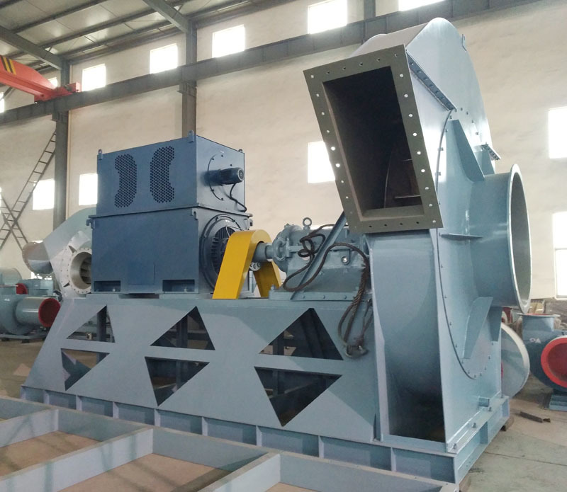
What is the principle of a centrifugal fan?
Release time:
2022-01-27
In the mechanical industry, centrifugal blowers are very large devices that are widely used and have brought us significant benefits. However, many consumers do not have a good understanding of centrifugal blowers. So, let's learn about the principle of centrifugal fans together!
In the machinery industry, centrifugal blowers are large devices that are widely used and have brought us significant benefits. However, many consumers do not have a thorough understanding of centrifugal blowers. Let's learn about centrifugal blowers together.Induced Draft FanWhat is the principle?

Centrifugal Induced Draft Fan
A centrifugal induced draft fan is a machine that increases gas pressure by converting mechanical energy input from a motor to deliver gas in parallel.Induced Draft FanIt is a type of fluid machinery. The working principle of a centrifugal induced draft fan is fundamentally similar to that of a turbo compressor, but due to the low gas flow velocity and small pressure changes, it generally does not require changes in gas specific volume, treating the gas as an incompressible fluid.
1. First, check the dimensions of the foundation and ensure the center dimensions of each cavity; the deviation of the foundation dimensions should be within 20mm, and the deviation of the center dimensions of each cavity should be between 10mm, using the main building reference point or the boiler's longitudinal and transverse centerline as a benchmark. The measured deviation of the foundation's longitudinal and transverse centerline should be 10mm, and the deviation of the centerline distance should be 3mm.
2. Level the foundation, place the anchor bolts, and install the shims. The shim set typically consists of 2 flat and 1 inclined shim, with the thicker ones placed below, and the inclined shims used in pairs; protruding about 20mm from the frame; after locating, they should be well welded and must not be loose; shims should be placed at the main load-bearing base plate of the equipment, at the vertical ribs of the frame, or on both sides of the anchor bolts, without affecting secondary grouting, as close to the anchor bolt holes as possible.
3. Rough positioning of the lower half of the casing: Pay attention to the manufacturer's installation marks, usually marked with 'a' and 'b', and distinguish the relationship with the inlet and outlet pipelines, as well as the rotation direction of the impeller before positioning.
4. Insert the collector's horn into the impeller and secure it with metal wire, then suspend the rotating assembly in the specified position; install the anchor bolts. The curvature of the anchor bolts should be L/100 (L is the length of the anchor bolt, assuming the lower end of the anchor bolt does not touch the bottom of the hole or the hole wall). The force on the anchor bolts should be uniform, with 2-3 threads exposed; then, release the metal wire and use bolts to secure the lower part of the collector and the lower half of the casing, adjusting the gap between the impeller and the horn.
5. Positioning of the blower rotating assembly: The verticality of the blower shaft to the casing hole is positioned as follows. Attach a magnetic piece to the shaft and place the dial gauge's head on the elastic end face of the bearing outer ring or bearing seat hole (on the upper cover machining surface); at this point, as long as the shaft rotates more than one full turn, the reading of the needle should be below 0.15mm, which indicates the verticality of the bearing box to the shaft.
6. Leveling and aligning the motor: Adjust the coaxiality of the fan and motor shafts (leveling and aligning the couplings). Use three dial gauges for alignment, two axially and one radially; rotate the shaft 90 degrees for each measurement, record the data, and measure the readings from top to bottom and left to right, adjusting the coaxiality to achieve an error of 0.05mm; additionally, a gap of 10mm is required between the two backrests and wheels. After locating, recheck the height of the shaft center and other data, and make records.
7. After positioning the fan, ensure the fastening of the upper half of the casing, the collector, and the installation position of the casing, and lay asbestos rope between the two casings; tighten the connecting bolts evenly at the corners; using the impeller as a reference, readjust the gap between the impeller and the horn.Induced Draft Fan8. Install the intake box, inlet regulating damper, and the remaining parts of the blower, ensuring the damper rotates smoothly. If it does not rotate smoothly, lubricating oil must be added before installation. During installation, the blades should be securely fixed and have sufficient expansion clearance with the casing; the adjustment operating device should be flexible and accurate, with consistent action, and the opening indicator should match the actual position; pay attention to the opening direction and do not install in reverse. The suction direction should be the same as the rotation direction of the impeller.
9. The configuration of the cooling water and lubricating oil pipelines should meet the requirements of the drawings, be correctly configured, clean, and free of debris inside the pipes.
The above introduces the principle of the centrifugal induced draft fan. It would be great if this could serve as a reference. In the future, if you need to purchase a centrifugal blower for use, the correctness of the installation ensures the normal operation of the centrifugal induced draft fan, so please pay attention to the installation issues.
Related News


